1SEI Automotive Europe GmbH
2Technical University of Lodz
Automotive industry is in the process of changing from conventional propulsion to electric drive. Introduction of high voltage circuits, voltage above 48V, brings new challenges to the design of the vehicle. One of those is the need to protect the harness from harmful ingress of moisture or particulates that would cause is to fail prematurely or cause a hazard for the end user. The usage of various materials for protection against foreign material intrusions can cause unforeseen issues, depending on the choice of materials for encapsulation and the level of protection required, be it over-moulding, potting or enclosure. In this article a case study of incorrect material choice will be presented with possible implications and what to do to avoid the problem from occurring in future endeavours. Incorrect choice of materials for enclosure can cause it to fail in its function due to differences in thermal expansions factors and the possibility can cause the destruction of the assembly.
In the development of electric vehicles, there has been a need to develop new ways to route the connections inside the vehicle. High voltage architecture has got its own challenges to overcome in order to be competitive in production. Using new types of connections and the usage of new materials to protect the connection between two lines.[1]
Examples for connections can be placed into the following groups:
Both connection types have their advantages and disadvantages. The direct connection is preferred in situations that require resistance to forces that might be transferred threw it during assembly of the system. The connection is done with the use of a type of a screw joint or Direct connection of two lines.[2] The negative of this type of connection is that it is hard to disassemble after the component has been installed and the insulation of both parts of the conductor have to be extended. Terminal connection offers a quick disassembly possibility but is more prone to damage coming from forces in the system, for example during assembly of the component. Also in case of high voltage systems it must be protected against sparking that could destroy the connector during disassembly. The need to protect the route of the connection especially their joints against the ingress of the elements be in particle pollutants or fluids that can either damage the conductor causing an increase of contact resistance or disrupt the connection completely [1]. Insufficient ingress protection can also cause water to travel along the conductor and cause damage to the devices that are interconnected by the line. Various method have been employed to try to prevent the phenomenon from occurring. One was to use of gaskets to prevent the ingress of pollutants into the system. The other that will be looked in more detail in this article will be encapsulation of a material with other material. This can be done in a multitude of methods. Over-moulding is the process in which a high temperature plastic is used to encapsulate the instance of interest by the means of injection of the plastic. For this method the same material or similar can be used for encapsulation. The drawback of the method is the requirement of using tooling for the injection moulding process this has a significant impact on the piece price, especially in case of low volume production. Potting [3] is a similar method to over-moulding. However in the case of potting the material is fed into the assembly under gravity or by the use of low pressure system. Hot melt is a form of using a low pressure and low temperature material for over-moulding, in comparison to pressures and temperatures in case of standard over-moulding. [4],[5] For all the above mentioned cases depending on the material used a phenomenon can be observed that leads to the systems ingress protection being compromised and in some cases the whole assembly being destroyed. [6] In this study we will try to explain the reason for the occurrence of the phenomenon and what can be done to prevent the failure mechanism from occurring. The case has been observed during a thermal shock test [7]. Test sample encapsulated in an over-moulded [8] material has been destroyed by a cable pushing threw the material after a series of cycles of the thermal shock. Simulation of thermal behaviour [9] of the materials and an explanation of what led to the destruction of the sample will be described further in this article.
2. Materials and Methods
The phenomenon has been observed during the thermal shock testing [7] of the sample. The sample has been constructed in order to test ingress protection for an encapsulation solution and it’s resistance to mechanical stress coming from sudden temperature changes. Sample has been constructed out of two conductors ultrasonically welded together to represent a joint. Conductive material is CuETP and insulation material is made of PA material. Encapsulant is made of modified PA6 material. Diagram of the sample’s construction has been illustrated in figure 1.
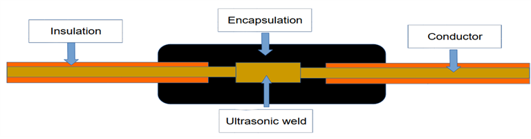
Figure 1. Test Sample.
This has been tested using thermal shock test according to DIN EN60068-2-14. Schematic of a thermal chamber with two chambers, one set to [Tmax] the second to [Tmin] can be seen in Figure 2.
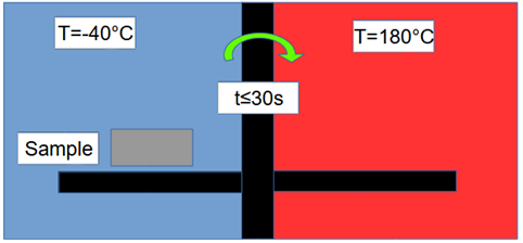
Figure 2. Test Chamber Schematic.
Maximum temperature has been selected to be 180 degrees, minimum temperature has been set to minus 40 degrees. The change time is less than 30 seconds and the dwell time was 15 minutes per temperature after the temperature stabilised. Number of test samples was set to 6, this is a standard amount in automotive industry testing n=6.
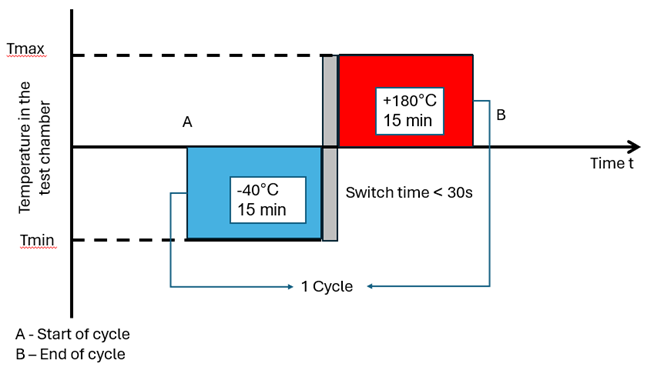
Figure 3. Thermal shock test graph.
3 Data preparation (Finite Element Method)
For the purpose of the simulation part of the model was used due to its symmetry. The part of the sample that was modelled can be seen in figure 4.
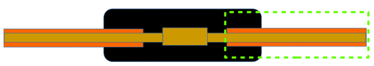
Figure 4. Part of sample used for FEM simulation.
In order to be able to properly model the phenomenon the following data had to be prepared. For example the following method can be used [10]
? Encapsulant: PA6
? Conductor insulator: PE
? Conductor: Copper
Sample length has been set to 100mm length for the conductor and insulator and the over-moulding material were set to 50mm in length. This was done to represent a sufficient encapsulation to prevent capillary pull of water into the uninsulated part of the conductor.[8]
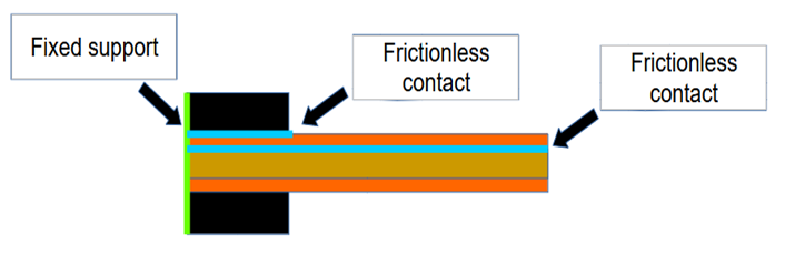
Figure 5. Boundary conditions
? Frictionless support at the connection planes between the different bodies.
• Element size has been set to 0.5mm as illustrated in figure 5. The complete amount of calculation nodes is 332318 and 72823 elements.
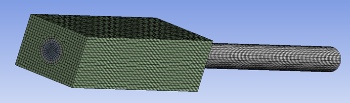
Figure 6. Mesh element size 0,5mm
• Sample has been heated up to 180 degrees in order to illustrate the relative increase in dimensions for the different materials.
4 Model results & verification
Calculation model has been prepared as a 3D section of the sample tested. This has been done in order to better visualise the phenomenon. Relative sizes had been kept. [17],[18],[19] Setup of the model described in section 3 has been used to simulate the behaviour of materials during the test. The model has been prepared, as mentioned, with a frictionless support to be able to visualise the difference in expansion coefficients of the different materials.
Figures 7,8,9 depict distortion of material in the 3 principal axis.
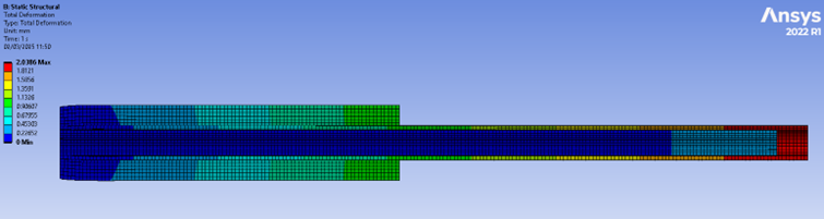
Figure 7. Thermal expansion rate, differences between bodies.
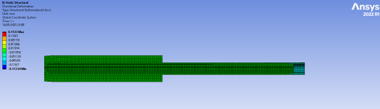
Figure 8. Thermal deformation in X-axis.
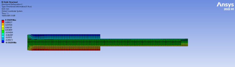
Figure 9. Thermal deformation in Y-axis.
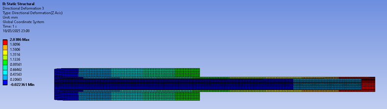
Figure 10. Thermal deformation in Z-axis.
The model depicts that the biggest expansion is for the insulation material. The next is the environmental protection material, conductor material is the one that expands the least. In the model it was possible to observe that the insulator has extended by approximately 2mm, next in regards to thermal expansion was the over-moulding material. It has expanded by approximately 1,2mm last was the conductor that had expanded by only 0,2mm. As can be seen in figure 10. This does confirm the laboratory observations.
5 Results & Discussion
It was observed that after 100 to 150 cycles samples were being destroyed. The failure occurred when a cable has been pushed through the encapsulating material. In the case study the material was a modified PA material used for the process of hot-melt over-moulding. Encapsulation has been done by over moulding a cable assembly with the aforementioned hot-melt material. Failure mechanism was found out to be caused by a specific order of thermal expansion and contraction during testing. In the heat up phase the material to heat up first was the conductor of the cable, due to good thermal conductivity of copper. Next was cable insulator, last to expand was the encapsulating material. Big role in the phenomenon was also the thermal expansion factor difference of the materials. This made the insulator expand significantly more than metallic conductor. During the cooling phase the same order caused the conductor to be pressed into the enclosure, initially be the insulator while contracting pressed the conductor in and next material of the casing further pressed it into the sample and prevented it from moving in the initial stages of heat up part of the cycle.
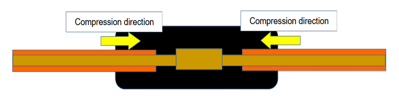
Figure 11. Failure mechanism 0-50 cycles.
Each cycle had caused the conductor to be pressed a bit more into the material, forcing it through the enclosure in the end. Figure 11 shows the initial status of the sample the conductor is being pressed inside the encapsulation.
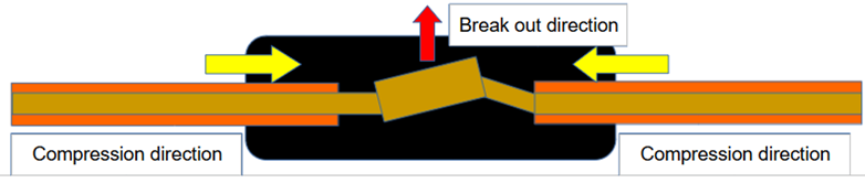
Figure 12. Failure mechanism 50-100 cycles.
In the middle of the testing process the weld knot had become distorted and depending on where friction was greater that side will act as the anchor point. Opposite side will start to press on the weld knot and start to distort it. This will in turn start to move one end of the knot towards the edge of the encapsulating moulding. This was represented in schematic in figure 12.
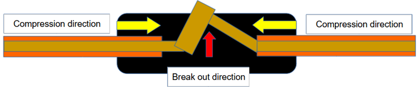
Figure 13. Failure mechanism 100-150 cycles.
After about 100 to 150 cycles the weld knot will be forced through the samples moulding material. As can be seen in figure 13. Break occurs in gradual steps as was presented in figure 14. It is possible to observe a gradual breaking line as the weld knot is gradually pushed through the plastic material. It has been established that the event occurred because the materials are all chemically inert and will not react with each other during processing. Chemical bond would ensure good protection against incursion of elements. The material used for case moulding did not bond chemically to the insulation material. Only method of ensuring contact between the two materials was a mechanical bond. Coming from pressure from shrinkage of materials after moulding process. During the thermal shock the material is being pressed in little by little. The conductor breakout occurred and the laboratory samples have had a beachhead break fracture of the over mould material.
From the observation of the phenomenon, it was possible to establish that the choice of material for ingress protection needs to be done with significant thought behind it. This phenomenon was not observed in the industry until now as the usage of high voltage systems became widespread with the introduction of electric vehicles. In case of low voltage circuits the operating temperatures were lower and this behaviour was not observed. The case of high voltage makes this even more important as the temperatures and implications of incorrect choice are more severe than in case of low voltage (below 48V) systems. Protecting material has to either be able to bond chemically with the insulation or have a similar thermal expansion coefficient to allow for both the materials to retain a mechanical bond during the life cycle of the component. Second possibility is to select a material that is more flexile so that it can accommodate the thermal distortions coming form the rapid change of temperature. This way bond between the materials can be retained as well as protection against elements. Failure to correctly select material can result as in case of this study in not only loss of intended function by the component but also in destruction of the component
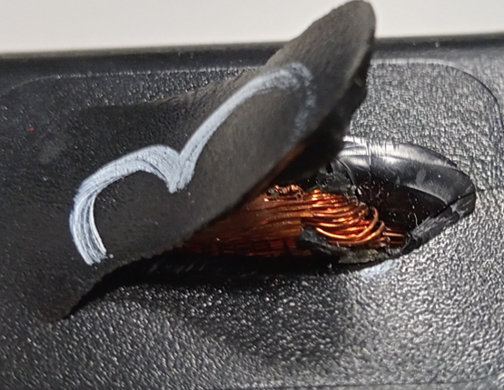
Figure 14. Break out of the conductor threw encapsulant.
What can be seen in figure14 is that the breakout had occurred in gradual steps. The beachhead lines of the gradual progression of the break out created by the conductor, slowly, in each cycle, cracking the encapsulating over-mould and gradually pushing threw the material.
6 Conclusions
It is important to choose correct materials when choosing protective material. If materials are not chosen in a correct way it may cause an unforeseen behaviour of the system like the phenomenon that had occurred. Materials chosen should have similar thermal expansion in order to expand and contract in a similar way, that will decrease the mechanical stress on the components. Alternatively, materials should have sufficient flexibility to be able to accommodate for the relative movement. Ideally material pairs should be chosen that they form a chemical bond or adhere to each other.
Lack of the above-mentioned conditions might lead to thermo-mechanical stress that in turn might lead breakage of mechanical bond between material parts and damage components causing loss of function or destruction of component like in the presented case. [17],[18],[19],[20] In the preparation of this article no GenAI tool have been used.
Author Contributions: Conceptualization, investigation, data validation, writing—original draft preparation Rafal Krawczyk; formal analysis Marcin ??cki and Grzegorz Górecki; data curation, Marcin ??cki and Grzegorz Górecki.; writing—review and editing, Marcin ??cki and Grzegorz Górecki.; supervision, ?ukasz Kaczmarek. All authors have read and agreed to the published version of the manuscript.”
Funding: This research received no external funding
Data Availability Statement: Exact laboratory data are the property of the SEI Automotive Europe GmbH.
Acknowledgments: The Authors would like to thank SEI Automotive Europe GmbH for their support.
Conflicts of Interest: Declare conflicts of interest or state “The authors declare no conflicts of interest.” Authors must identify and declare any personal circumstances or interest that may be perceived as inappropriately influencing the representation or interpretation of reported research results. Any role of the funders in the design of the study; in the collection, analyses or interpretation of data; in the writing of the manuscript; or in the decision to publish the results must be declared in this section. If there is no role, please state “The funders had no role in the design of the study; in the collection, analyses, or interpretation of data; in the writing of the manuscript; or in the decision to publish the results”.
Abbreviations
The following abbreviations are used in this manuscript.
REFERENCES

Rafa? Krawczyk*, Marcin ??cki, Grzegorz Górecki, ?ukasz Kaczmarek, Thermal expansion of materials in High Voltage applications and possible failures coming from incorrect choice, Int. J. in Engi. Sci., 2025, Vol 2, Issue 12, 12-21. https://doi.org/10.5281/zenodo.18844351
 10.5281/zenodo.18844351
